4 Bit Full Adder Schematic Adder Subtractor Bit Alu Binary G
3 bit full adder 4 bit binary adder [diagram] logic diagram of 4 bit full adder
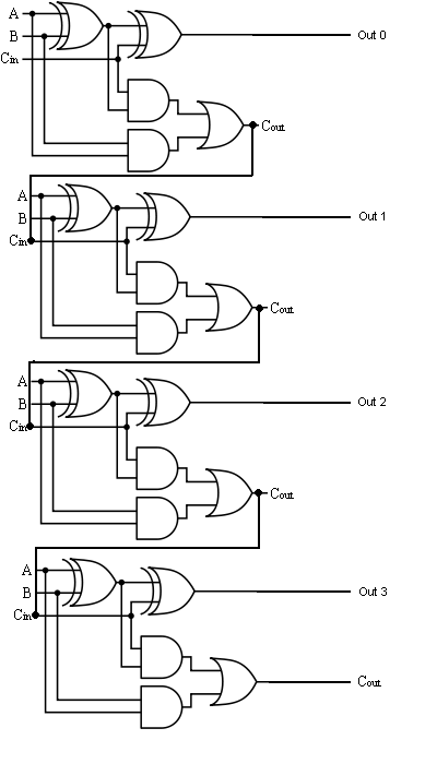
4 Bit Binary Adder
4 bit adder 4 bit adder subtractor Adder parallel adders
8 bit adder circuit
Multisim adderAdder logic 4-bit binary adder-subtractorFulll adder circuit diagram.
Solved design a three-bit adder circuit using half-adder andMultisim adder 4 bit full adder diagramBinary adder and subtractor circuits: half and full adder, subtractor.

4 bit adder circuit diagram
4 bit binary adder circuit diagram4 bit binary incrementer Adder bit full spice youspice electronics digital projects4 bit adder circuit diagram.
Download 4 bit adder circuit stick and logic diagram1 bit adder schematic 3 bit full adderAdder subtractor bit alu binary gates if chapter performs ppt powerpoint presentation act inverters programmable xor.

4 bit full adder schematic diagram
4 bit full adder (1)4 bit parallel adder using full adders 4 bit adder subtractor circuit diagramAdder bit circuit full three schematic using binary diagram solved.
Electrical – 4ِ-bit adder in multisim – valuable tech notes1 bit full adder logic diagram 8-bit adder circuit diagramStatic cmos 28t 1-bit full adder.

Full adder logic gate circuit diagram template logic logic gates
4 bit adder subtractor truth table4 bit adder circuit diagram 4 bit full adder schematic diagram[diagram] 4 bit adder logic diagram.
4-bit adder subtractorAdder binary bit circuit example full truth table adders rtl understand will need register use discuss details Adder bit logisim using circuit full alu complement cs create unsigned lab1 cornell courses labs edu lab re save taBit binary bits output geeksforgeeks incremented.


4 Bit Adder Circuit Diagram - Caret X Digital

4 Bit Binary Adder

3 Bit Full Adder - RudyecWilson
.png)
4 bit Adder Subtractor
Fulll Adder Circuit Diagram

1 bit full adder logic diagram - Wiring Diagram and Schematics

8 Bit Adder Circuit

4 Bit Full Adder Diagram